If you don’t know what a xDrip device is take a look at this page.
 I was tickled by someone on Reddit who linked to yesterday’s blog about the components required for a xDrip which was entitled “An “Amateur” builds a module for DexDrip”. So here it is, this amateur’s guide to building an xDrip/DexDrip. (The article actually referred to DexDrip as that what xDrip was called at the time.)
b) xDrip is a DIY product, decide for yourself if you wish to use it. Build it, test it, test it again and use (if you want to) in conjunction with a certified receiver.
c) The fact that it is working for us does not mean it’s right for you.
d) Never build a xDrip for anyone else and never sell one.
e) The blogs are provided for information only. We are not endorsing it for use by others, nor promoting it, just merely publishing our information as well as answering questions from previous blog articles.
A baptism of fire heat
Although I received lots of offers of help to solder the components together the guys at work told me I’d have no trouble doing it myself, so I decided to try.
First I ordered the soldering kit (iron, solder, stand, helping hands, solder sucker) from eBay and a practice board to train myself with. The ‘helping hands‘ turned out to be worth their weight in gold.
I soldered my first pin, inspected it and then soldered three more, choosing to solder them right next to each other as it seems that a common problem for amateurs is putting too much solder on. With four pins soldered I tested everything for continuity issues, to make sure no excess solder had spilled on to the adjacent contacts and shorted anything out.
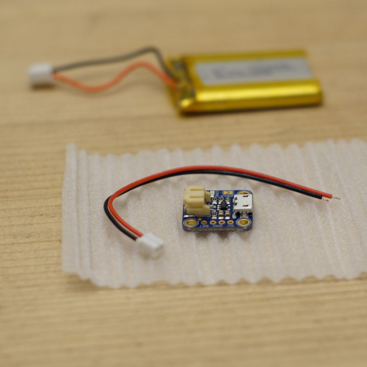 Attach LiPo-charger connector to battery
My AdaFruit LiPo-charger came with a connector, my battery came with a connector; they weren’t the same.
First job then was to cut the wires from each and solder the battery wires to the LiPo-charger connector.
NOTE: some people remove the connector terminal on the LiPo-charger and solder directly onto the charger board, I didn’t fancy this as I like to be able to disconnect batteries and swap them easily.
DO NOT connect battery to LiPo-charger.
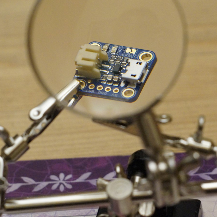
 Solder wires to AdaFruit charger
The AdaFruit Li-Po battery charger then needed a power (red) and ground (black) wiring up.
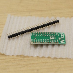
For my first try I soldered a four-piece-header-pin to the board and used jumper wires to connect to it, but within a week I removed the header pins & soldered the wires directly onto the PCB.
1. Red wire, solder on to 3.3v (marked as BAT on mine), first on the left as we look at that board. Make sure you don’t solder on to the 5v connector.
2. Black wire, solder on to one of the GND connectors, for ease I chose the 3rd from the left.
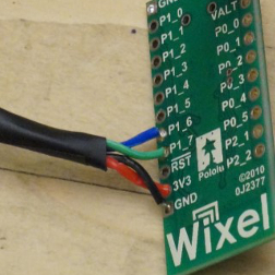 Connect wires for bluetooth module to WIXEL
Prepare four wires (red, black, green, blue) with one female header pin at one end and bare wire for soldering at the other.
1. Black, solder to GND
2. Red, solder to 3V3
3. Blue, solder to P1_6
4. Green, solder to P1_7
Other possible options: The header pin option is the simplest way to connect from WIXEL to HM-10.
The hardest (but not too bad) option is to desolder the HM-10’s header pins, then solder wires with two bare ends onto the WIXEL and to the HM-10.
The middle option is to solder wires with two bare ends, one end onto the WIXEL and one bare end onto the relevant header pin on the HM-10. Whilst this might seem easy I think it’s simpler to desolder the HM-10s header pins as above.
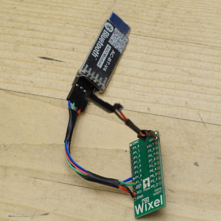 Connecting the HM-10 Bluetooth module
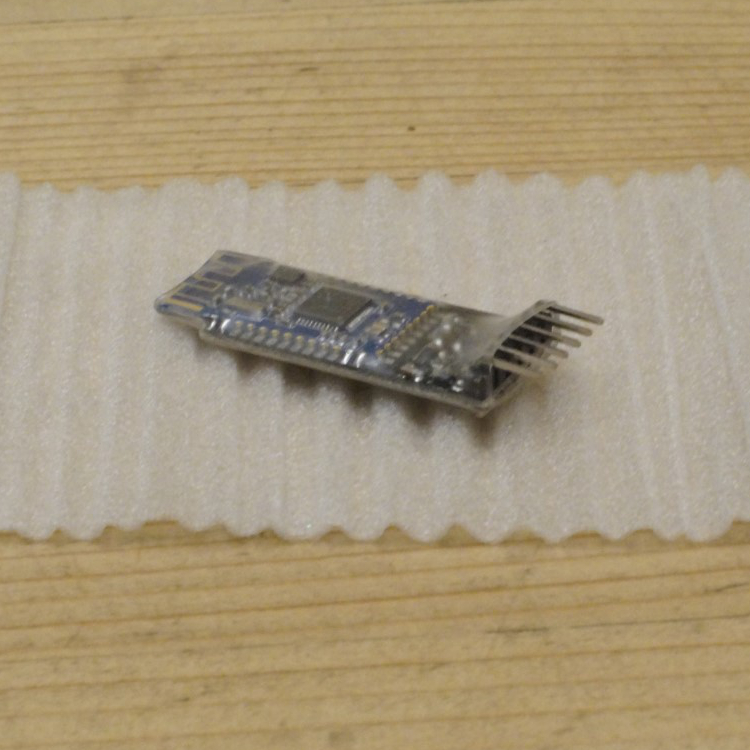
What you do next depends on what you chose to do on the ‘Connect wires for bluetooth module to WIXEL’ step:
If you soldered wires with female header connector at one end when you did the step above then all you need to do next is to slide the correct colour wire’s connector onto the correct HM-10 pin as per the diagram here.
If you soldered wires with two bare ends and left the header pins on the HM-10 then you need to solder the bare wire ends to the correct HM-10 header pin as per the diagram here. This is tricky to do (for me) but not impossible as I found when I made a second xDrip. I choose to wrap electrical tape around each soldered pin/wire afterwards.
If you soldered wires with two bare ends and removed the HM-10 header pins then just solder the bare ends onto the HM-10 as per the diagram here.
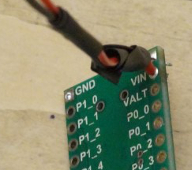 Solder LiPo-charger wires to WIXEL
With the LiPo-charger disconnected from the battery (and micro-USB power) you now need to solder its wires to the WIXEL.
Red, solder to VIN
Black, solder to GND
Hopefully by the end of it you’ll have something that looks like this:
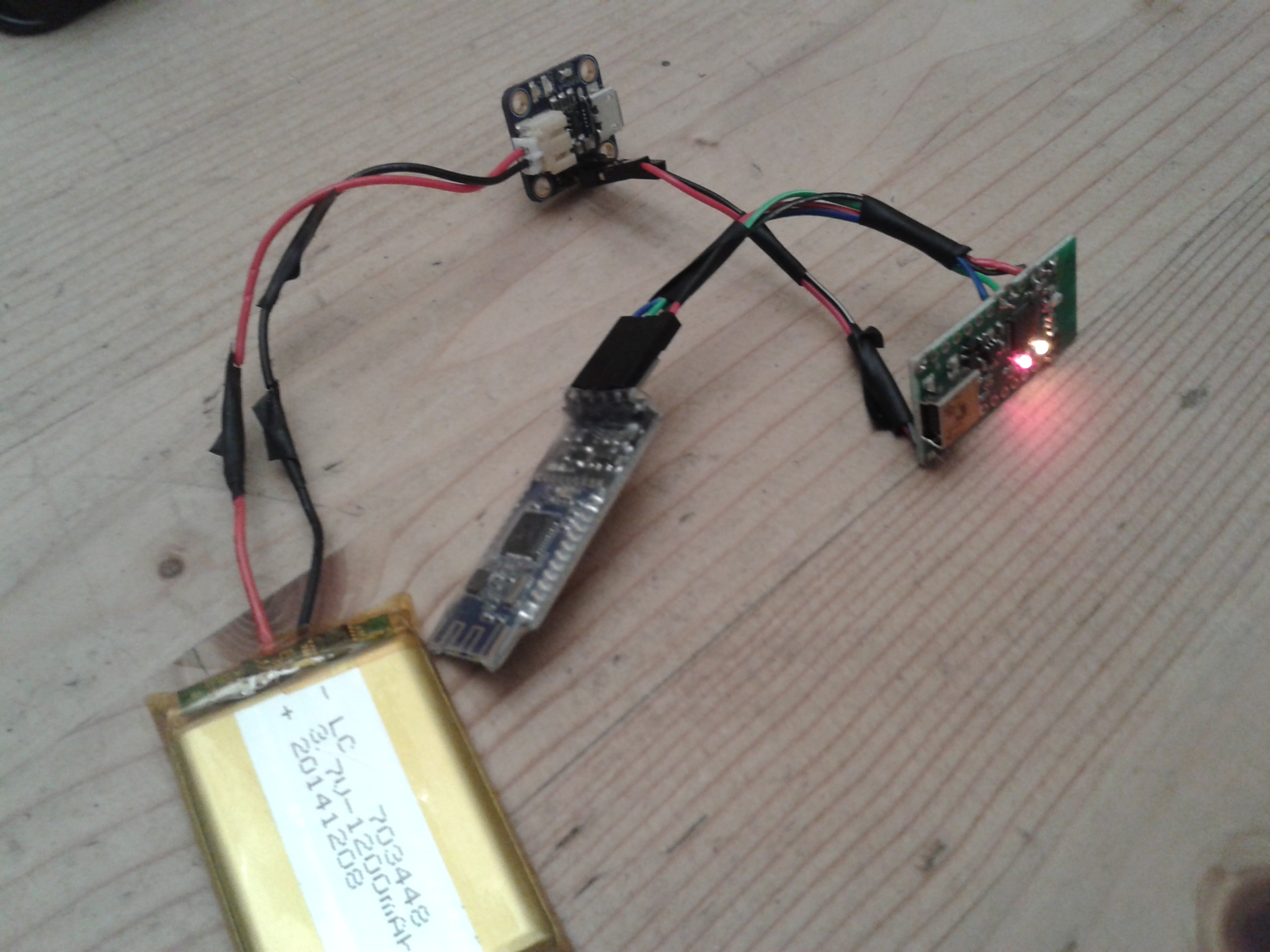
Note: the picture shows header pin connections for the AdaFruit Li-Po charger but I’ve now soldered the wires directly to the board, it now has a much smaller footprint.



Hi Kev, I want to build this but have hit a problem finding the Bluetooth module. I ordered an HM-10 which turned out to be CC2541 not CC2540 as advertised. In any case it didn’t have any pins/holes I have the skills to solder to.
Just wondering if you’ve found any new source for them.
Thank you
Robert
Hi Robert, sorry but I don’t know of a legitimate source which has current stock.
Thank you. I’m currently trying to get a CC2541 working. Will let you know if I’m successful.
Happy to report that my xDrip is now working thanks to @StephenIsTaken ‘s CC2541 experimental code.
Anyone that have tried this http://www.adafruit.com/product/1697?
Allan, did you ever get an answer to your question or did you build the xDrip with that bluetooth LE and got it to work?
Not sure about Allan but I’ve never seen anyone using this board for the bluetooth element of xDrip.
Thank you Kev! I couldn’t find any of the other BLEs in Toronto area. I will use this module and post my result.
Can you order from USA sites?
Hi Kev, I’ve also ordered 2 HM10s from Aura and received CC2541s. I’ve tried running the firmware upgrade above, but I’m unable to access the CC2541 via the com port. I think I may have broken the solder pads. You mentioned using multimeter to check the contacts are not over soldered. How did you do this? When you did get a working unit, how did you identify the MAC access of the bluetooth adaptor? Many thanks, Tim
Steven Black’s latest xDrip app works with the CC2541 ble devices.
http://stephenblackwasalreadytaken.github.io/xDrip/
You don’t need to upgrade the firmware.
Thanks Robert. I decided to keep the existing CC41 as a practice board for my soldering and returned the untouched backup CC41 to Aura. I didn’t want to have a dependence of particular code revisions in future. I managed to get an original HM10 with backboard from eBay. Hopefully I will be able to get up and running this weekend.
Tim
the LiPO charger i got has 4 pins on the back labeled VUSB, D-, D+, and GND, int that order. Absent a pin labeled BAT, which one do i solder the red wire from VIN on the Wixel to? It’s a Jaycom JS-1965
Sorry, I’m not sure, I didn’t use that one.
I could be wrong, but I think it’s Jaycon rather than Jaycom. http://www.jayconsystems.com/micro-usb-lipo-charger-mcp73831.html has Datasheets and schematics which should help answer your question.
HTH
Tim
That did answer my question, Thank you.
New question: my HM10 didn’t come with the voltage regulator board or the pre-soldered pins. I found the pinout for the HM10 and i see corresponding P1_6 and P1_7 names on it. Am i correct in understanding that the p1_6 (USART 1 TX) on the wixel connects to the p1_7 (UART_RX) on the HM10 and P1_7 (USART 1 RX) on the wixel connects to the P1_6 (UART_TX) on the HM10?
Could someone tell me how does the voltage measurement modification works?
Sorry Svet, I’ve no idea, I’ve not done that myself. Have you asked in the Facebook group ‘CGM in the Cloud’?
Printable case:
http://www.thingiverse.com/thing:1481048
Can you provide a better view of the connection to the HM10. Or a description. You talk about connecting the Wixel with a nice picture but the view of the HM10 and which pins to use is not provided. Much appreciated. Thanks.